Cable connection details DIN harness details By Annon 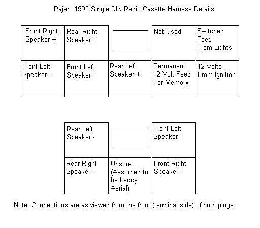
You will notice that the front left speaker - has 2 connections. This is correct. they are linked out, possibly for a "poverty model" radio with only one speaker so that only one plug has to be connected to the back of the radio.
The lower middle connection on the smaller plug I have assumed to be for an electric aerial. I don't have one on my Paj and the original radio did not output a 12v signal on switch on, However because it's the only connection not accounted for and the only one left..... But please, check it!!
Please Note: The drawing above is correct for my 1992 Paj that came with the single DIN sized Computer Controlled 4 speaker radio cassette.
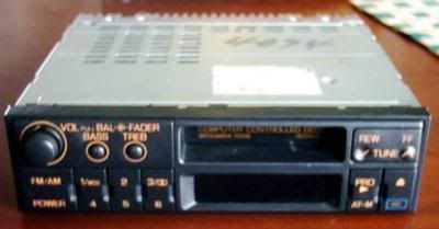
If you can't find an "adaptor" or don't want to use one to connect a new Radio/Cassette player... and if your old R/C player is like the one I had (see photo below)... then the following may be helpful ... Don't trust the Japanese wire colour coding!! (Green for live! and black&white for Ground )
The old R/C player's Front.
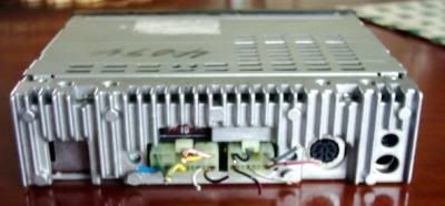
The old R/C players's back.
The old R/C player's wiring NUMBERED (see decoding below!)
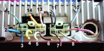
“Decoding” the wires on the back of the ORIGINAL Pajero Radio / Cassette Players. Total of 14 wires!! (two were redundant! No. 6 and 12)… See above photo for numbers on wires.
8: thin black white - Ground / electric aerial output
2: thick blue - ACC (+ve) +12V supplied to unit when switch key is turned to ACC
3: thin blue - Battery (+ve) +12V supplied to unit ALL time unless battery is dead!
4: thick yellow blue - Rear Left Speaker (-ve)
10: thick white blue - Rear Left Speaker (+ve)
14: thick yellow red - Rear Right Speaker (-ve)
9: thick white red - Rear Right Speaker (+ve)
11: thin black blue - Front Left Speakers (-ve)… comes from both door and dash speakers!
5: thin white blue - Front Left Speakers (+ve)… comes from both door and dash speakers!
7: thin black red - Front Right Speakers (-ve)… comes from both door and dash speakers!
13: thin white red - Front Right Speakers (+ve) … comes from both door and dash speakers!
1: thin green - The new unit operates perfectly WITHOUT this wire! It turned the old unit's illumination ON, when sidelight are turned ON!
6: thin black red - redundant!! No contact to the unit underthere, and the wire comes from number 12!!
12: thin black red - redundant!! the wire goes to number 6 which is not connected to unit !!